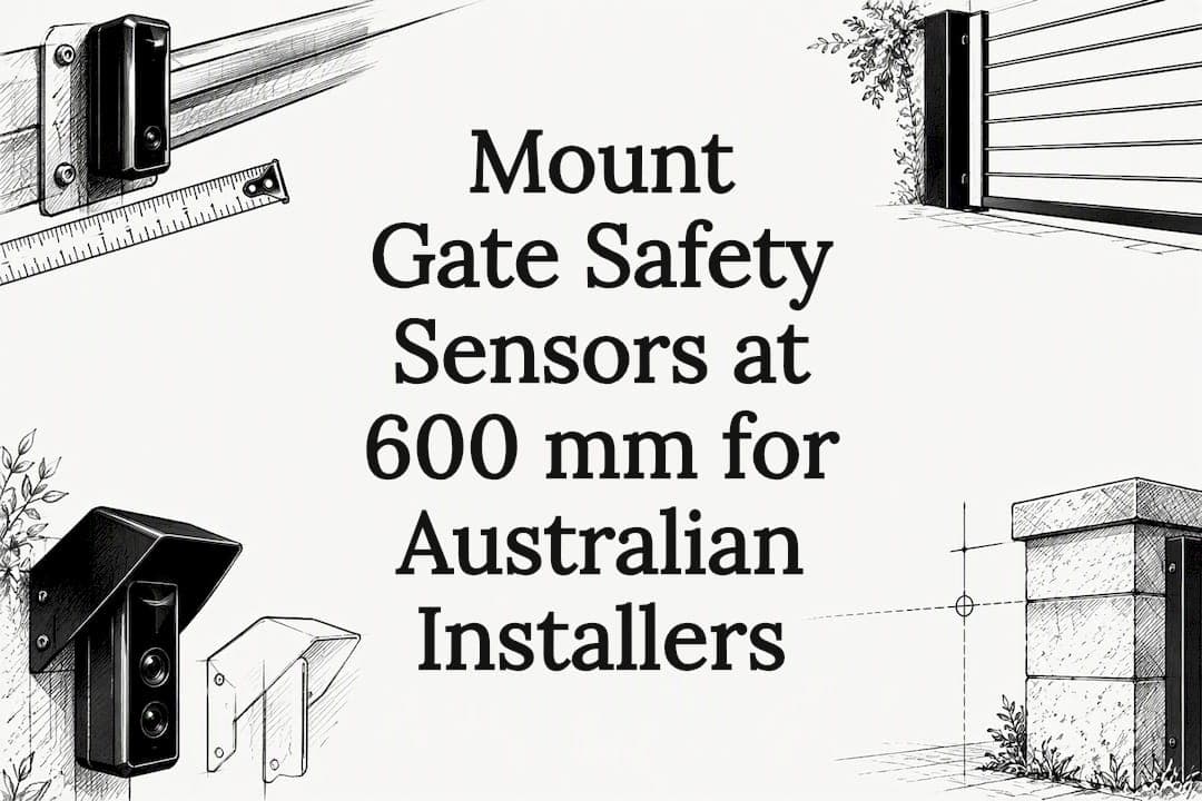
The right setup uses three device types together: photoelectric beams, safety edges, and inductive loops, each covering a different failure point. Photoelectric beams typically sit close to the gate panel and are commonly mounted at a height suitable for pedestrian detection, roughly around half a meter to two-thirds of a meter above ground. No single sensor protects the whole gate, so alignment checks and scheduled maintenance matter as much as the initial placement.
TL;DR:
- Proper sensor placement involves mounting photoelectric beams close to the gate panel at about two feet high to prevent entrapment and ensure reliable detection.
- When installing sensors, visually confirm alignment and perform movement tests to detect drift caused by ground movement, weather, or physical impact.
- On sliding gates, mount beams along the travel path and use safety edges on moving surfaces; swing gates require coverage of arcs with additional beams or loops to prevent blind spots.
- Environmental factors like sun glare, rain, fog, and dirt can impair sensor performance, so selecting sensors with appropriate IP ratings and regular lens cleaning is essential.
- Certification and safety depend on comprehensive testing, proper installation, documentation, and integration of sensors with control systems, especially in high-traffic or commercial settings.
Table of Contents
- Sensor types and when to use each
- Photoelectric beam placement: heights, proximity to gate, and alignment checks
- Placement rules by gate type: sliding gates vs swing gates
- Inductive loops and safety-edge placement details
- Alignment, commissioning tests, and simple maintenance checks
- Installer responsibilities, handover checklist, and Gatecon's approach
- Common environmental factors affecting sensor performance
- Regulatory standards and compliance requirements for gate safety sensor placement
- Integration with existing gate automation systems and control units
- Recommendations for sensor placement in high-traffic or commercial vs residential settings
- Error troubleshooting specific to sensor placement
- Author perspective: prioritizing safety with design
- Gatecon's approach to sensor placement and handover
- Sources
- FAQ
Sensor types and when to use each
Every automated gate needs more than one kind of detection because no single device covers every risk. Photocells, or through-beam sensors, send an infrared beam across the gate opening and stop the gate when something blocks it. Reflector sensors do the same job with a single housing and a mirror, useful where wiring both sides is impractical. Safety edges are pressure-sensitive strips fitted to the leading edge of a moving panel, catching contact injuries that a beam positioned too high or too low would miss. Inductive loops, buried in the driveway, detect vehicles by mass and metal content rather than by line of sight, so they keep working in fog or direct sun. Some commercial sites add ultrasonic, radar, or laser scanners for wide-area monitoring, though these are less common on residential driveways.
- Photocells stop pedestrian entrapment in the beam's direct path.
- Safety edges catch shearing and crushing at the panel's moving surfaces.
- Inductive loops detect vehicles regardless of light or weather conditions.
Pro Tip: Match each device's IP rating to its mounting location. Exposed beams near garden beds or road spray need a higher rating than sensors under an eave.
Photoelectric beam placement: heights, proximity to gate, and alignment checks
Photoelectric sensors work best when mounted close to the gate panel and at a height that catches the body, not just the feet. DASMA technical guidance lists common mounting heights ranging from roughly 4 to 27 inches above ground, with mounting distance typically within about 5 inches of the gate panel. For most residential driveways, a single beam pair near 600 mm above finished ground handles pedestrian detection well.
Best practice recommends keeping photoelectric sensors no higher than about two feet above the ground and close to the gate panel, which helps minimize potential entrapment zones.
For sites with a mix of low-profile cars and taller vehicles or trailers, stagger two beam pairs at different heights, or install a through-beam assembly across a long or exposed span where a single reflector sensor would struggle with alignment drift.
- Sight both beam units visually to confirm they face each other directly.
- Walk an object through the beam path and confirm the gate stops immediately.
- Watch for intermittent operation in rain or fog, a sign the beam alignment has drifted.
Placement rules by gate type: sliding gates vs swing gates
Sliding and swing gates create different entrapment zones, so device placement differs between them. On a sliding gate, mount beams along the full travel path, fit safety edges on the leading face and any point where the panel meets a post or fence line, and position approach and exit loops far enough back to detect a car before the gate starts moving. On a swing gate, place beams to cover both the outside and inside of the closing arc, add a beam beyond the fully open position to catch anyone standing in the swing path, and use shadow or reverse loops to cover the blind spot created by the arc itself. Our comparison of sliding and swing mechanics covers how these movement patterns affect everyday use as well as sensor coverage.
- Double-leaf inward swing: beams on both leaves plus a shared loop covering the full opening.
- Single swing opening outward: an extra beam set beyond the arc to catch pedestrians walking past.
- Long sliding gates: multiple beam pairs along the track rather than one pair at the opening.
Inductive loops and safety-edge placement details
Loops and edges do the work that beams cannot. Elsema's guidance on loop detectors recommends installing loops on both the inside and outside of the gate opening, giving the system a reliable way to detect a vehicle approaching and one already inside before the gate closes. A reverse or holding loop under the gate itself prevents the panel from closing on a car that has stopped in the opening.
Safety edges belong on every leading and trailing edge that could pinch a hand or catch clothing, wired directly to the control board so contact triggers an immediate stop and reverse.
- Place approach loops far enough from the gate to allow a full stop-and-reverse cycle.
- Keep loops clear of metal posts and reinforcing mesh, which cause false triggers.
- Route edge wiring through flexible conduit to survive repeated gate movement.
Pro Tip: Test each loop with the actual vehicles that use the driveway, a motorcycle or small hatchback can sit below a loop's sensitivity threshold if it was tuned for a heavier car.
Alignment, commissioning tests, and simple maintenance checks
A correctly placed sensor still needs commissioning before anyone trusts it. Check mechanical clearance around the gate's full travel, interrupt each beam with an object at several heights, confirm the control board responds within the expected time, and test force limitation on the leading edge where the opener allows it.
Regular testing is part of a documented safe system of work, something WorkSafe Victoria has pursued enforcement action over following a fatal crush linked to inadequate gate safety testing.
- Homeowners should test beam interruption and edge response monthly.
- Book a full installer service annually to check alignment and wiring.
- Record sensor locations, test dates, and results for future reference.
Keep a note of the isolation switch location alongside these records, since a technician arriving months later needs to find it quickly.
Installer responsibilities, handover checklist, and Gatecon's approach
A proper handover leaves the homeowner able to operate and understand every safety feature, not just the remote. BFT's Australian and New Zealand guidance recommends locating the isolation switch within three metres of the gate so it stays quick to reach in an emergency.
- Demonstrate the manual release procedure before leaving the site.
- Point out the isolation switch and confirm it sits within three metres of the gate.
- Walk the client through each sensor's location and purpose.
- Document mounting positions and heights for future servicing.
On bespoke installations, concealed mounts and discreet hoods can be fitted around beams and edges, choosing IP-rated devices that hold up outdoors without disrupting the gate's line. Our architectural gates work shows how detection hardware sits within a custom design rather than bolted on top of it.
Common environmental factors affecting sensor performance
Weather and site conditions change how well a sensor actually performs, regardless of where it's mounted. Direct sunlight hitting a photocell receiver can wash out the infrared signal, causing missed detections right when the beam should be working. BMGI's installer guidance notes that photocells are effective, but only when facing and IP rating are matched to the site, since sun glare and rain both cause false readings if ignored.

Rain and fog scatter infrared light and can make a beam appear intermittently blocked even with no obstruction present, which is often mistaken for a wiring fault rather than a weather issue. Dust and pollen buildup on the lens has the same effect over time, gradually weakening the signal until the gate stops responding reliably.
Mitigating these issues starts with orientation: face beam transmitters and receivers away from direct east or west sun where possible, and use a hood or overhang to shade the lens. Choose sensors with an IP rating suited to direct weather exposure rather than relying on a sheltered mounting position that might change with landscaping. Clean lenses on the same schedule as other outdoor hardware, since a five-minute wipe prevents a service call. Inductive loops avoid most of these problems entirely, since they sit underground and detect by mass rather than light, which is one reason they pair well with photocells on exposed driveways.
Regulatory standards and compliance requirements for gate safety sensor placement
Gate safety sensor placement isn't just a design choice, it sits inside a broader set of safety obligations that installers and property owners both carry. BFT's Australian and New Zealand safety guidelines recommend combining photoelectric beams, safety edges, and torque or force limitation on gate openers, since each addresses a different entrapment risk across the gate's travel path. No single device satisfies the full set of recommendations on its own.
Compliance isn't only about hardware choice. It extends to documented testing, correct handover procedures, and keeping records that show the system was checked and working at installation. When that documentation is missing, the consequences are real: WorkSafe Victoria charged a gate repair company following a fatal crush, an enforcement action that industry professionals point to as a reminder that safety testing and a documented safe system of work aren't optional extras.
For anyone commissioning a gate, the practical takeaway is to ask an installer which combination of devices they're using, where each one sits relative to the gate panel, and how they document testing and handover. A gate that closes smoothly but has no beam, edge, or loop protection is not compliant with the guidance that governs the industry, even if it looks finished.
Integration with existing gate automation systems and control units
Every safety device on a gate ultimately reports to the control board, and how well that integration works determines whether the sensors actually protect anyone. A photocell wired incorrectly, or one plugged into a terminal the control unit doesn't monitor for faults, can fail silently: the gate keeps operating as if nothing is connected.
Most modern control units have dedicated terminals for photocells, safety edges, and loop detectors, each with its own fault-monitoring logic. When a beam is interrupted, the board should stop and reverse the gate immediately rather than pausing. When a loop detects a vehicle, the board should hold the gate open rather than starting a close cycle. Confirming these responses during commissioning, not just confirming that a light turns on, is what separates a properly integrated system from one that merely has sensors attached.
Retrofitting sensors onto an older control unit sometimes means the board lacks a monitored input for a given device type, in which case relay modules can bridge the gap, though this adds a point of failure that needs its own testing. For homeowners integrating gate automation with broader smart home systems, platforms like SmartSavvyHome cover how access control and automation devices talk to each other without compromising the gate's own safety logic. The safest approach treats the gate's safety sensors as a closed loop with the control board, tested independently of whatever smart home layer sits on top.
Recommendations for sensor placement in high-traffic or commercial vs residential settings
A single-family driveway and a commercial entry gate face different risks, and placement should reflect that difference rather than following one template everywhere. Residential gates typically see a handful of vehicle movements a day and occasional pedestrian traffic, so a standard beam pair near 600 mm, safety edges on the leading edge, and one set of approach and exit loops usually covers the site.

High-traffic commercial or multi-tenant sites need more coverage because more people and vehicles pass through in less predictable patterns. That often means multiple beam pairs at staggered heights to catch everything from a pedestrian to a delivery truck, dedicated pedestrian gates separated from vehicle lanes entirely, and additional loops positioned to prevent tailgating, where a second vehicle follows too closely behind the first through an open gate. Commercial sites also tend to justify radar or wide-area detection where the opening is broad enough that beam pairs alone leave gaps.
The practical rule: match the device count and placement density to how the gate is actually used, not to its size alone. A wide residential driveway gate used by one household needs less redundancy than a narrower commercial gate cycling dozens of times a day.
Error troubleshooting specific to sensor placement
Most sensor faults trace back to placement rather than a defective unit. False triggers, where the gate stops or reverses with nothing in the way, usually point to sun glare hitting a photocell receiver, a loop picking up interference from a nearby metal post, or a beam pair slightly out of alignment after ground movement or a knock during landscaping work.
Blind spots are the opposite problem: the gate closes on something it should have detected. This often happens when a single beam pair sits too high for a low object, or when a safety edge doesn't extend the full length of the panel's leading edge. Checking the beam height against the DASMA-recommended range and confirming edges run the full travel path resolves most of these gaps.
Intermittent faults that appear only in certain weather point to environmental interference rather than wiring. A gate that behaves normally on clear days but stops responding in rain or fog almost always has a photocell alignment issue worsened by weather, not a genuine fault in the beam itself. Loops that trigger inconsistently near dawn or dusk sometimes have wiring routed too close to power cables, which introduces electrical noise. Working through placement first, before assuming a component needs replacing, resolves the majority of these calls.
Author perspective: prioritizing safety with design
Sensor visibility and protected zone coverage often pull in opposite directions. A concealed beam looks better on a custom gate, but hiding it wrong shrinks the zone it actually covers. I'd rather see a slightly visible sensor doing its job than a hidden one that misses. Skipping proper testing isn't a design choice, it's a liability.
— Rhys
Gatecon's approach to sensor placement and handover
Getting sensor placement right on a custom gate means solving two problems at once: keeping the gate looking the way it was designed to look, and making sure every beam, edge, and loop sits exactly where it needs to. Gatecon builds sensor placement, commissioning, and full user handover into every project rather than treating them as an afterthought once the gate is installed.

That means concealed mounts and discreet hoods where a bespoke design calls for them, IP-rated devices chosen for the site's actual exposure, and a handover that walks the homeowner through manual release, the isolation switch, and every sensor's location before the project is signed off.
- Custom gates with sensor placement integrated into the original design, not retrofitted.
- Full commissioning and testing documented at handover.
- Ongoing service support for alignment checks and maintenance.
| Service | What it covers |
|---|---|
| Architectural Gates | Bespoke gate design with integrated automation and safety sensor placement |
| Designer Fencing | Fencing packages that complement gate projects |
| Custom Packages | Whole-entry design and installation for residential and commercial projects |
Readers ready to move past research and into a real project can start with an assessment through our service areas page.
Sources
- BFT Australian & New Zealand safety guidelines (PDF)
- Selection and Placement of Photoelectric Sensors for Automated Vehicular Gates — DASMA TDS-377 (PDF)
- WorkSafe Victoria news: Gate repair company charged after fatal crush
- Elsema — Loop detector
- BMGI — Safety beams for automatic gates
FAQ
Where should photoelectric sensors be placed on a gate?
Photoelectric sensors work best mounted within about 13 cm (5 in) of the gate panel and around 600 mm (24 in) above the ground, based on DASMA's placement guidance. This positioning minimizes the gap where a person or object could get trapped between the sensor's detection zone and the moving panel.
How do I know if my gate sensors are misaligned?
Misalignment often shows up as intermittent operation, especially in rain or fog, or as a gate that never stops when the beam path is blocked. Installer guidance notes that sun glare and weather exposure make alignment drift more noticeable over time, so a sudden change in behavior after a storm or landscaping work is worth checking.
Where is the best mounting location for a gate motion sensor?
Mount beam-based sensors facing directly across the gate opening, close to the panel itself, rather than angled or set back from the travel path. For vehicle detection, inductive loops embedded in the driveway on both sides of the opening, as recommended by Elsema's loop detector guidance, work better than motion sensors alone since they aren't affected by lighting conditions.
How high should a gate safety sensor be mounted?
Common industry practice places photoelectric sensors between roughly 4 and 27 inches above ground, with 24 inches (61 cm) as a practical upper limit for the sensor closest to ground level. The exact height depends on whether the gate needs to detect pedestrians, vehicles, or both, which is why staggered beam pairs are common on driveways with mixed traffic.
Do I need more than one type of safety device on my gate?
Yes. Australian and New Zealand safety guidance recommends combining photoelectric beams, safety edges, and torque or force limitation, since each device addresses a different entrapment risk along the gate's travel path.